Industrial Property
Own technology
Our technologies are specifically designed to facilitate the on-site construction of lattice structures with tubes.
Royalties
Technology protection stimulates the transfer of knowledge and rewards our R&D efforts.
Competitiveness
Patents, industrial designs and know-how are part of our assets that facilitate access to market.
METHODS FOR ASSEMBLING A LATTICE STRUCTURE
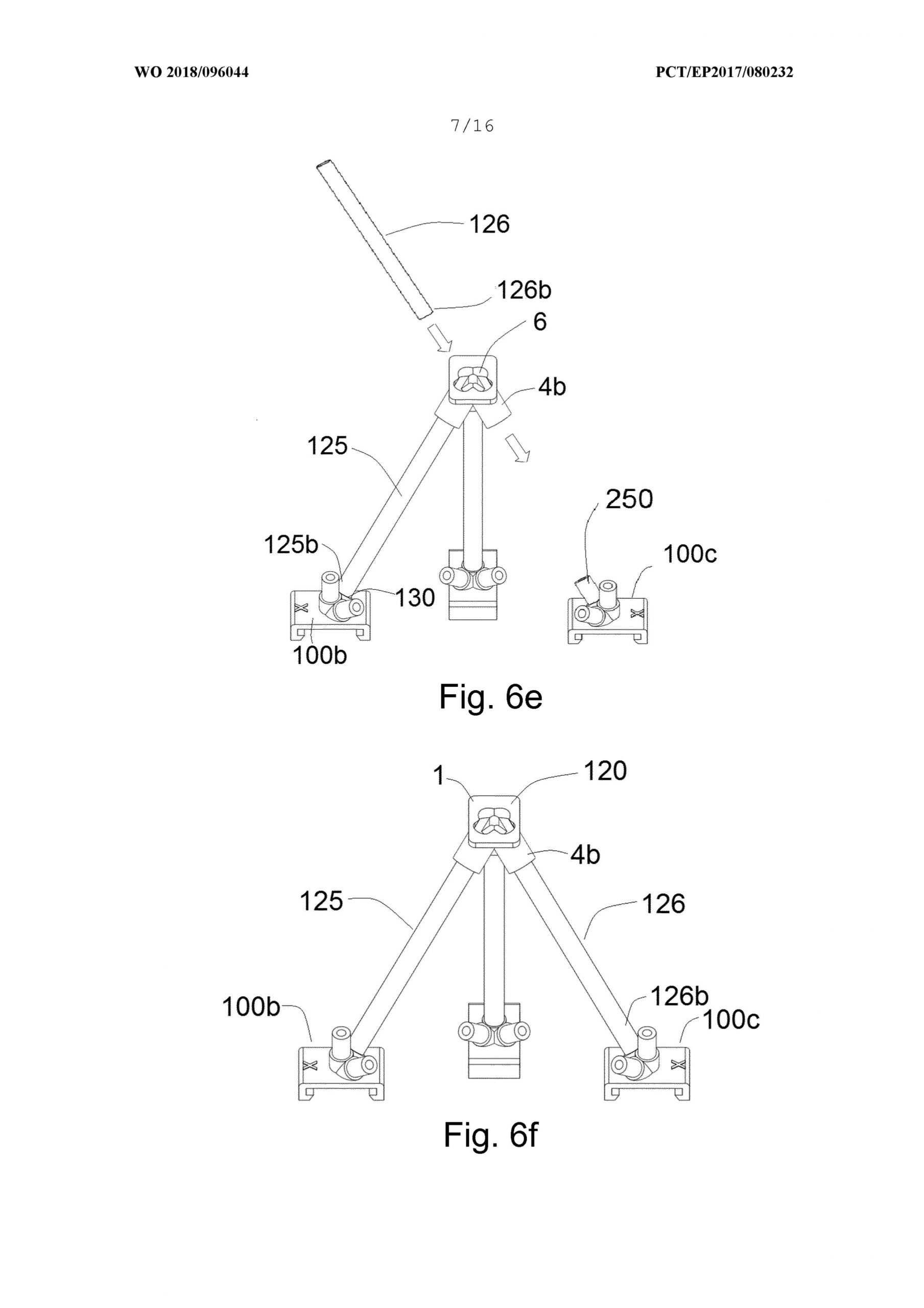
Methods for assembling a lattice structure are provided. The method comprises providing at least three node elements and two or more elongated bars. The method includes displacing a first elongated bar of the elongated bars, in a first direction, such that the proximal end of the first elongated bar is inserted into a hollow insertion channel of a first node element and displacing a second elongated bar of the elongated bars, in a second direction, such that the proximal end of the second elongated bar is inserted into a hollow insertion channel of a second node element. The method further comprises: displacing the first elongated bar in a third direction, opposite to the first direction, such that the distal end of the first bar is inserted into a corresponding hollow insertion channel of a third node element. Methods for disassembling a lattice structure are also provided.
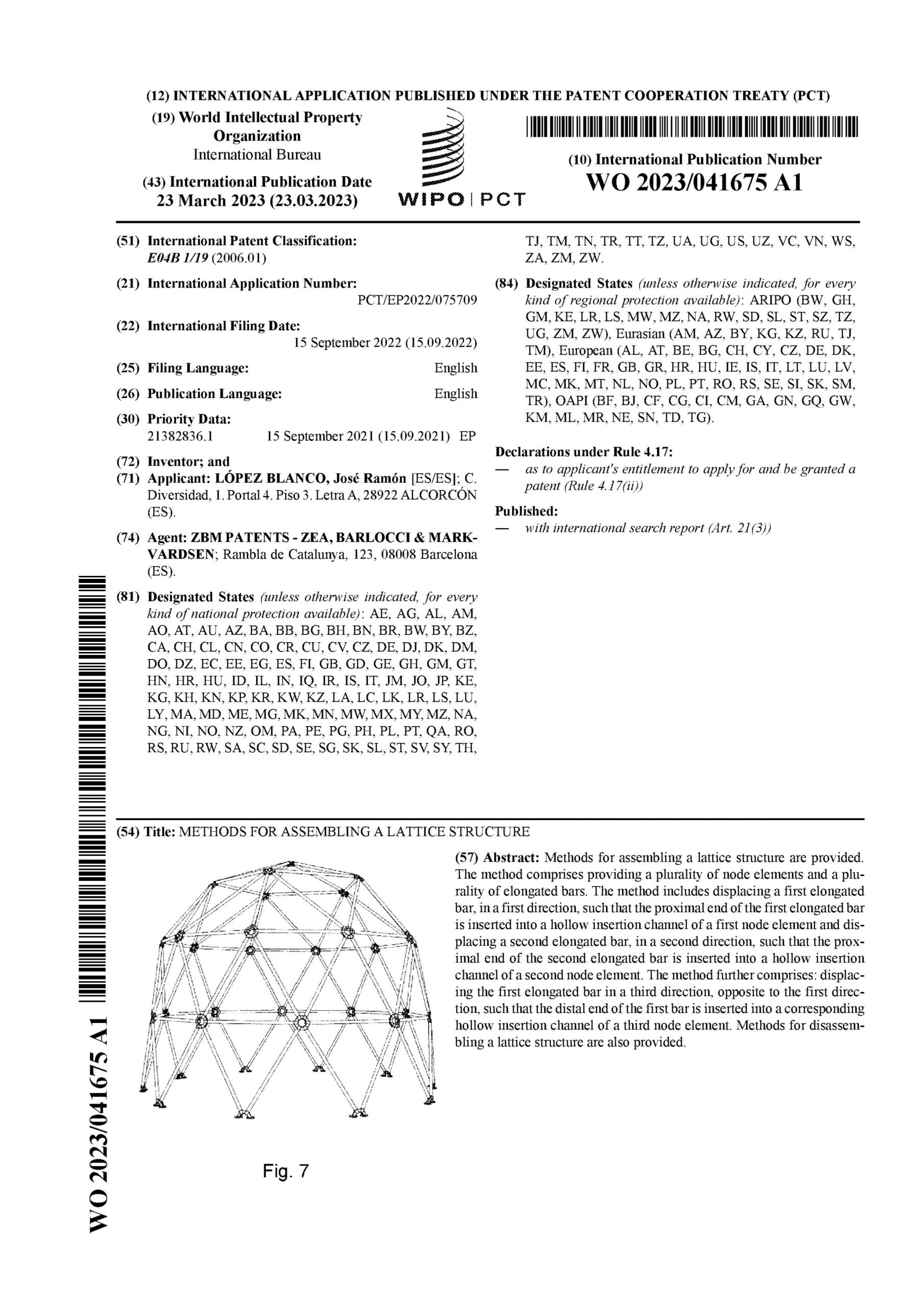
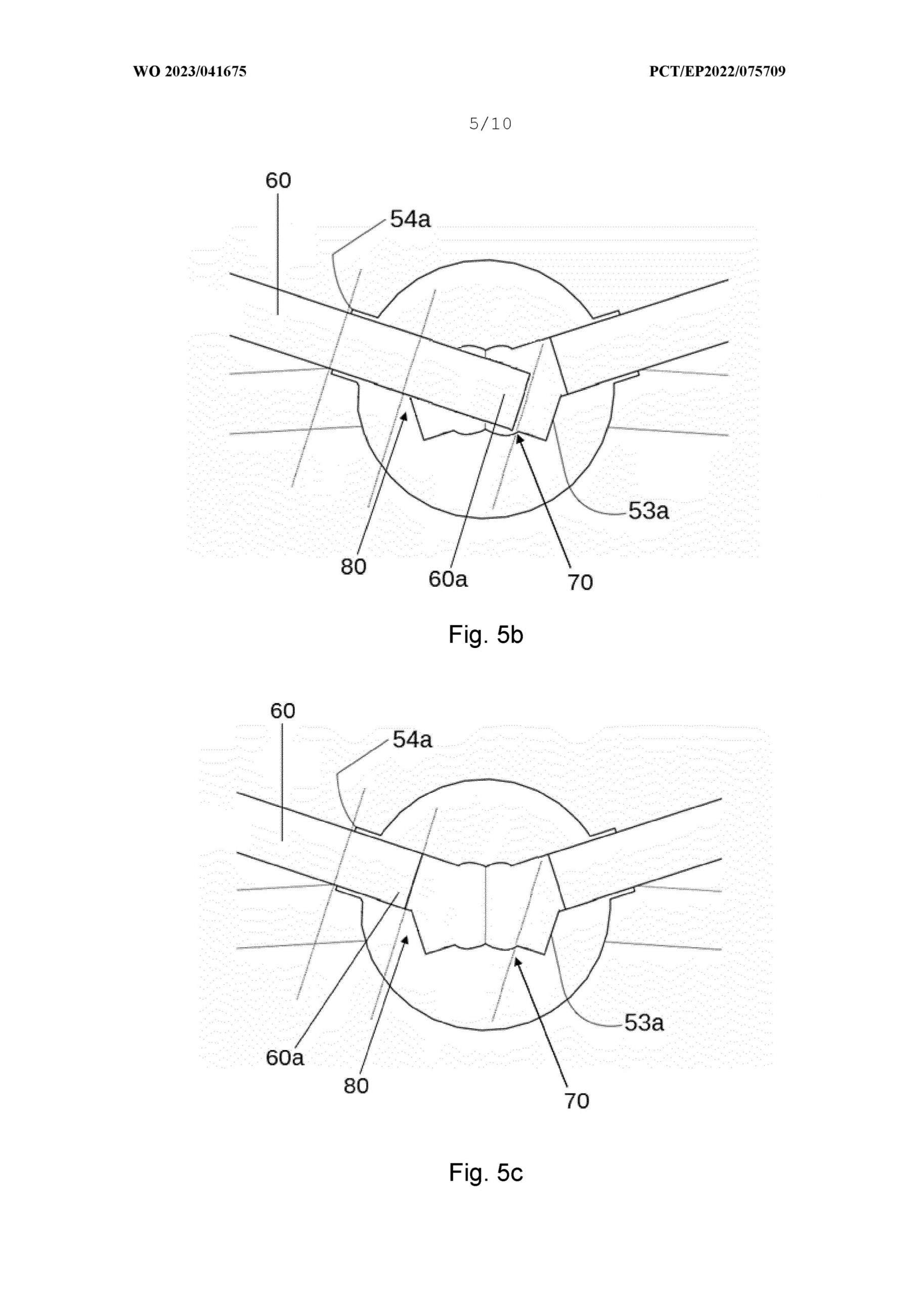
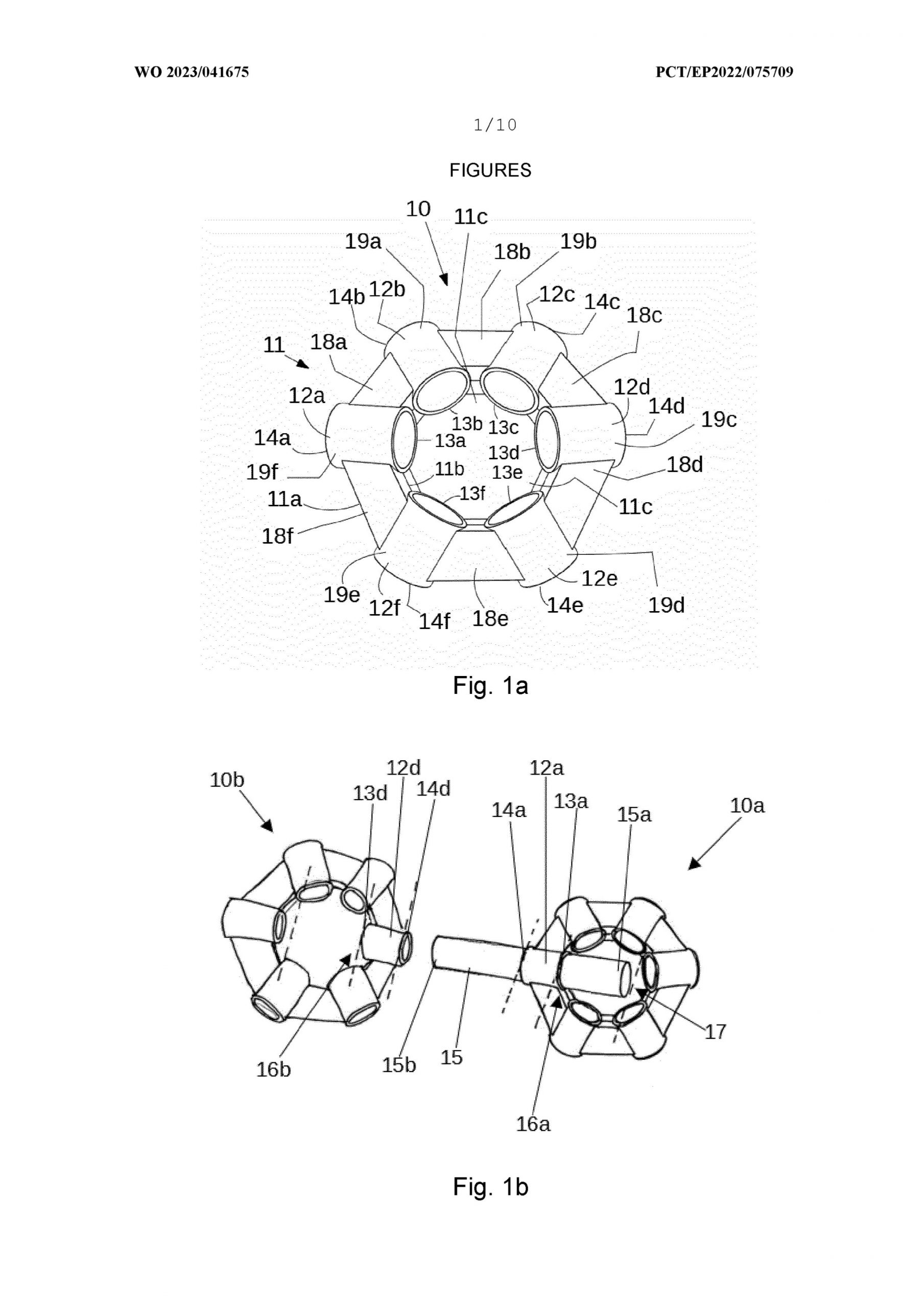
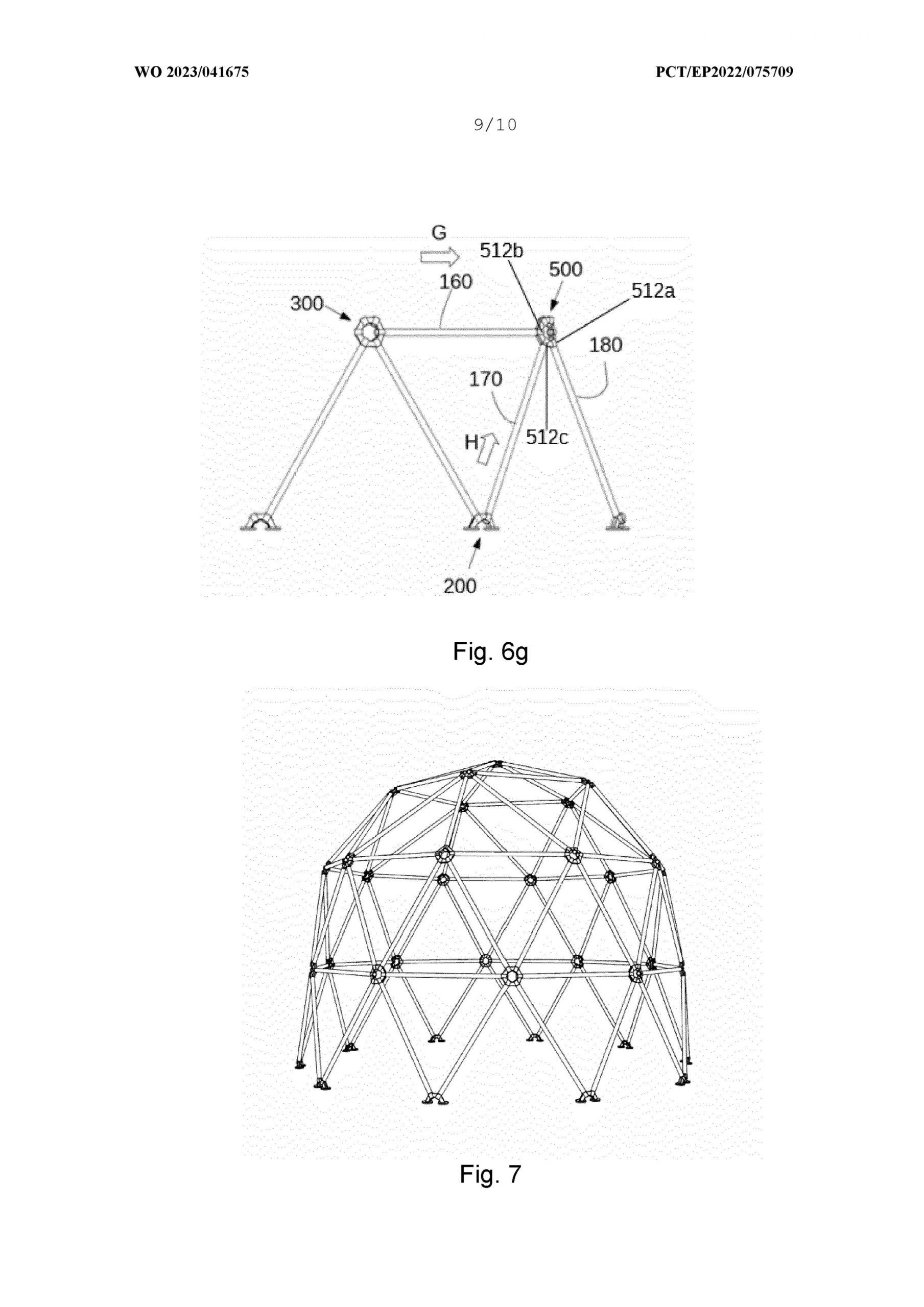
This video briefly introduces our latest general method for the cost-efficient assembly of lattice structures.
It may be especially useful for markets where high performance, rapid assembly, and low cost are a must.
NODE ELEMENTS, KITS, AND METHODS
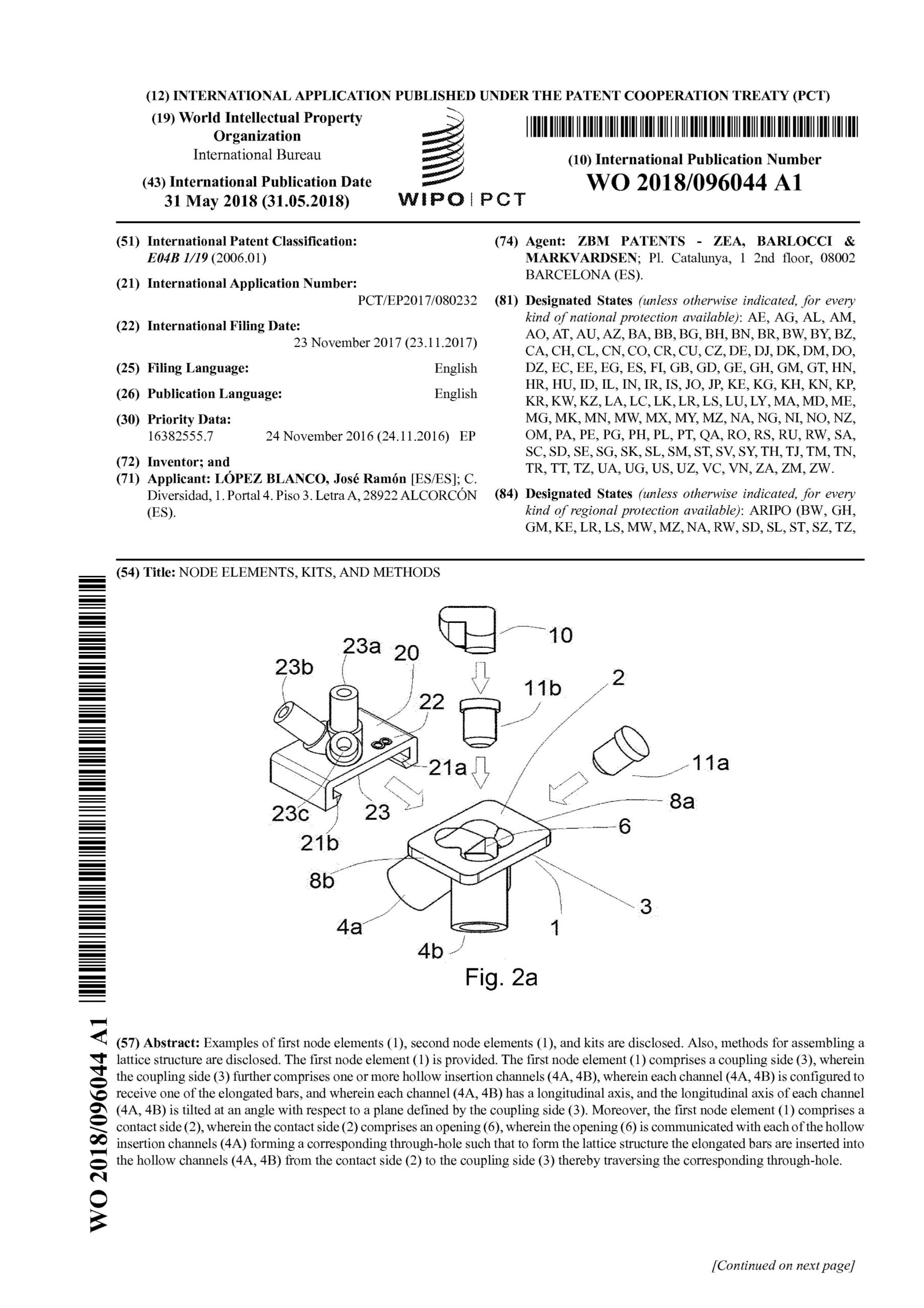
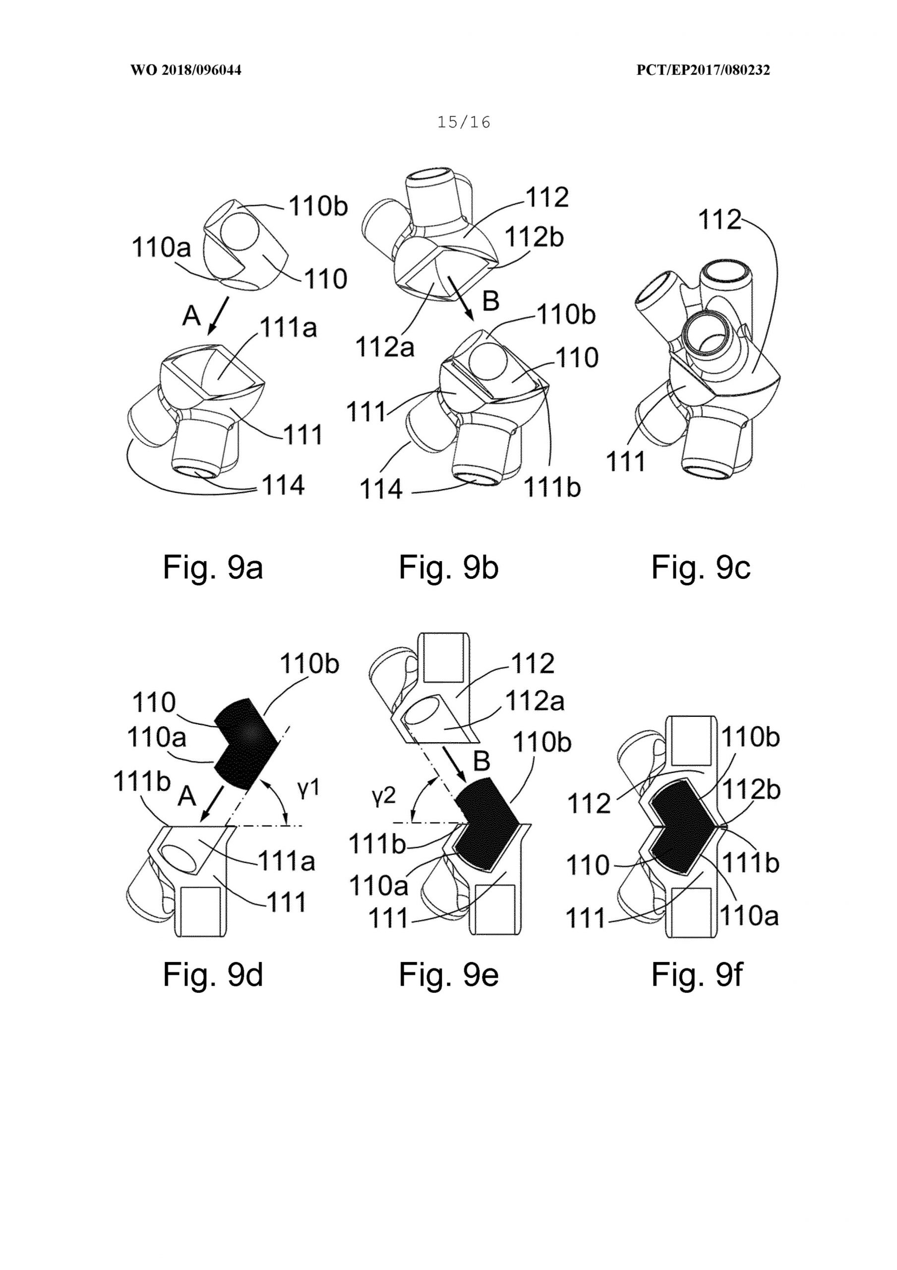
Examples of first node elements (1), second node elements (1), and kits are disclosed. Also, methods for assembling a lattice structure are disclosed. The first node element (1) is provided. The first node element (1) comprises a coupling side (3), wherein the coupling side (3) further comprises one or more hollow insertion channels (4A, 4B), wherein each channel (4A, 4B) is configured to receive one of the elongated bars, and wherein each channel (4A, 4B) has a longitudinal axis, and the longitudinal axis of each channel (4A, 4B) is tilted at an angle with respect to a plane defined by the coupling side (3). Moreover, the first node element (1) comprises a contact side (2), wherein the contact side (2) comprises an opening (6), wherein the opening (6) is communicated with each of the hollow insertion channels (4A) forming a corresponding through-hole such that to form the lattice structure the elongated bars are inserted into the hollow channels (4A, 4B) from the contact side (2) to the coupling side (3) thereby traversing the corresponding through-hole.
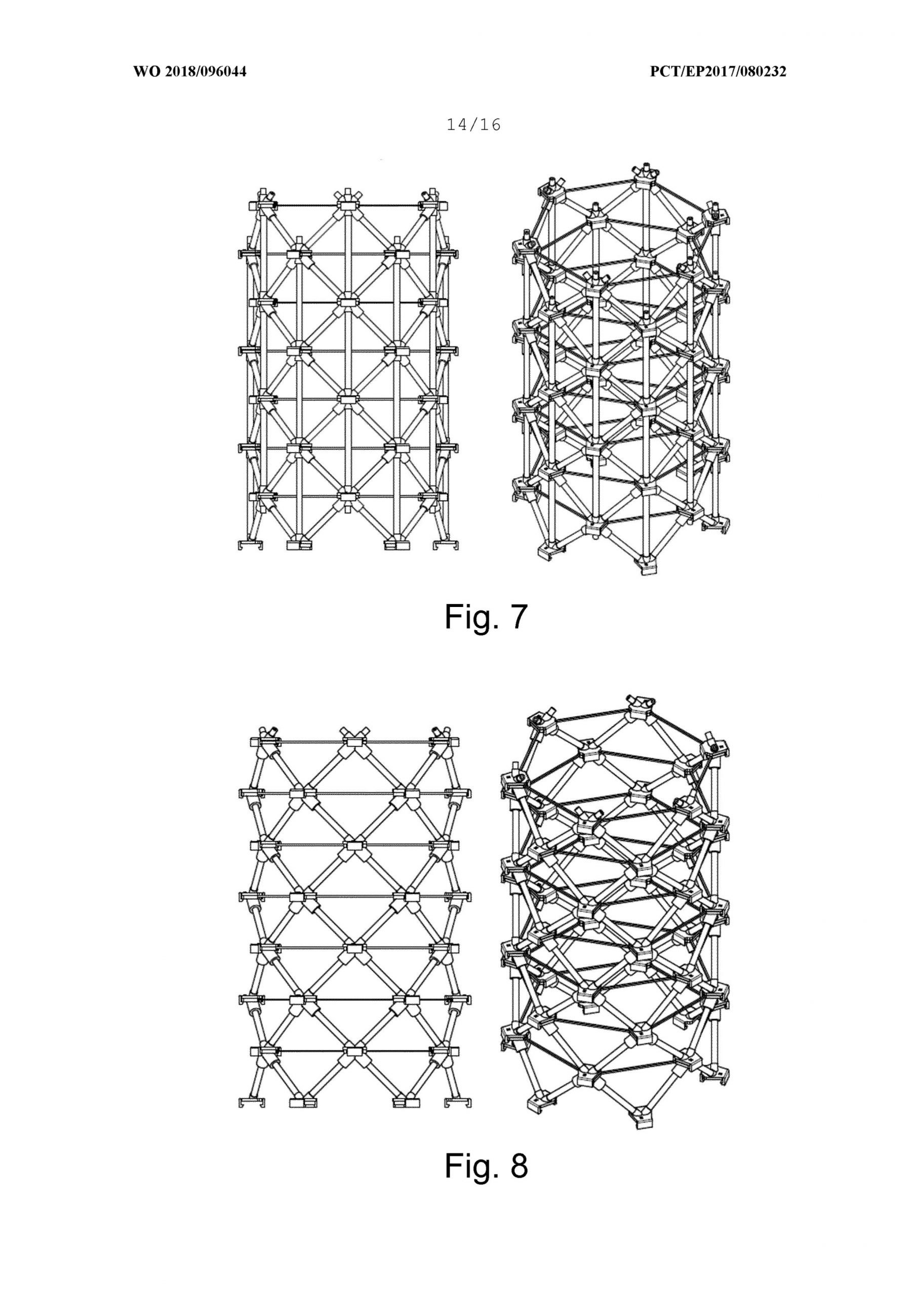
The on-site assembly of lattice structures is specially challenging for tubes and other kind of hollow profiles.
In this simplified animation, we have illustrated how our first Anisopter patented system (nodes and method of assembly) facilitate such process with a very simple example.
POWER PYLONS
Four variants have been registered to protect the new Anisopter power pylon concept.


